Thermal insulation
Design criteria, function
The purpose of thermal insulation in buildings is to maintain a comfortable
and hygienic indoor climate at low ambient temperatures. An minimal amount of
thermal insulation is required to protect the constructional elements against
thermal impact and moisture related damage. The main aim of thermal insulation
in winter is energy conservation leading to a decrease in heating demand and
hence the protection of the environment. This aim has to be considered in new
buildings as well as in renovating the building stock. Strategies to reach this
aim are the use of building materials with low thermal
conductivity ![]() -values
and the installation of windows with low U-Values
(see Windows) on the on side and the avoidance of thermal
bridges and uncontrolled infiltration (see Ventilation)
on the other side. Besides the above mentioned purpose, thermal insulation plays
a major role in preventing summertime overheating of buildings through reducing
the transmission of solar radiation, absorbed on the buildings exterior surfaces,
to the interior. The lowest
-values
and the installation of windows with low U-Values
(see Windows) on the on side and the avoidance of thermal
bridges and uncontrolled infiltration (see Ventilation)
on the other side. Besides the above mentioned purpose, thermal insulation plays
a major role in preventing summertime overheating of buildings through reducing
the transmission of solar radiation, absorbed on the buildings exterior surfaces,
to the interior. The lowest ![]() -values
of non evacuated elements achievable is the one of motionless air. Hence the
basic principle in developing insulation materials is to enclose as much non-moving
air into the structure of the material as possible and still satisfy the structural
stability required. The lowest achievable
-values
of non evacuated elements achievable is the one of motionless air. Hence the
basic principle in developing insulation materials is to enclose as much non-moving
air into the structure of the material as possible and still satisfy the structural
stability required. The lowest achievable ![]() -values
of insulation elements are realised with evacuated insulation panels.
-values
of insulation elements are realised with evacuated insulation panels.
Parameters related to building physics
The thermal properties of structural elements are characterised by the mass
density ![]() ,
the
,
the ![]() -values
of the building elements layers and the heat
transfer coefficients
-values
of the building elements layers and the heat
transfer coefficients ![]() at the surfaces. The heat transmission through an element is defined by the
air to air heat transmission coefficient U. Reducing the
at the surfaces. The heat transmission through an element is defined by the
air to air heat transmission coefficient U. Reducing the ![]() -value
of a material or increasing the thickness of the insulation layer results in
an decreasing U-value. The heat transfer coefficients are composed of a convective
and a radiative part. The heat transfer mechanisms are shown in Figure 1.
-value
of a material or increasing the thickness of the insulation layer results in
an decreasing U-value. The heat transfer coefficients are composed of a convective
and a radiative part. The heat transfer mechanisms are shown in Figure 1.
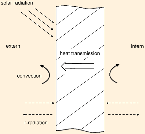 |
| Figure 1: Thermal transfer mechanisms of an exterior partition in the heating season.. |
The hygroscopic properties are defined by the resistance to water vapour migrations
number ![]() .
.
![]() quantifies
the resistance of a material against the migration of water vapour. To guarantee
a positive moisture balance, the insulating materials have to be open to diffusion
and have to absorb and release moisture quickly.
quantifies
the resistance of a material against the migration of water vapour. To guarantee
a positive moisture balance, the insulating materials have to be open to diffusion
and have to absorb and release moisture quickly.
|
||||||||||||||||||||||||||||||||||||||||||||||||||||||||||||
| Table 1: Selected material properties of insulating materials [1]. |
Figure 2 shows the decrease in the U-value as the thickness of the insulation layer increases. The U-value of a constructional element decreases rapidly as the first few centimetres of insulation are added. An further increase in insulation thickness does not always lead to an equally fast decrease in the U-value. The thicker the insulation layer already is, the less the decrease in the U-value is by further adding insulation.
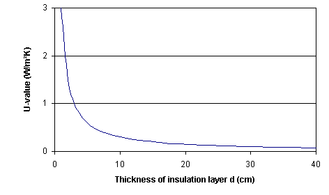 |
| Figure 2: Decrease in the U-value with increasing thickness of the insulation layer. |
Constructural requirements of insulation materials concerning the structural
stability and the constancy of shape are characterised by the dynamic stiffness
s`(MN/m²) and the thermal coefficient of longitudinal deformation ![]() L.
L.
Types of thermal insulation
Thermal insulation is implemented as opaque or transparent constructional
elements depending on the requirements. Opaque constructions can consist of
evacuated or non-evacuated insulating elements. In the vacuum, the heat transfer
mechanisms are restricted to the transport of energy through radiation. It is
therefore possible to achieve better U-values in relation to the insulation
layers thickness. The ![]() -value
of an evacuated panel is five to six times smaller than that of non-evacuated
insulation materials. Because of their high production cost the use of evacuated
panels is very limited.
-value
of an evacuated panel is five to six times smaller than that of non-evacuated
insulation materials. Because of their high production cost the use of evacuated
panels is very limited.
In the region of radiators, exterior walls can be coated with reflective materials to enhance the reflection of the long wave radiation of the radiator into the room and to reduce the absorption on the exterior wall.
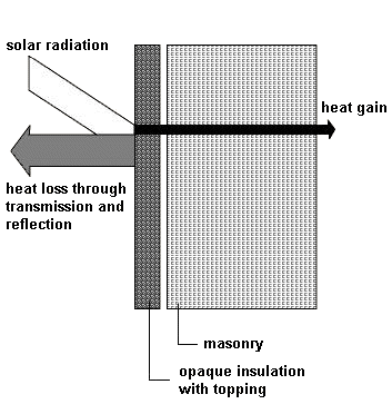
Transparent thermal insulation enables the passive use of solar energy on exterior walls. The short wave solar radiation passes through the transparent insulation material and reaches the wall partition behind and heats it up. The long wave radiation emitted from the partition cannot pass through the insulation layer, because the transparent insulation layer is opaque for infrared radiation. Figure 2 displays the energy pathways in opaque and transparent insulation constructions in a qualitative manner. Depending on the ambient temperatures, the heated up exterior surface of the wall leads to an reduced transmission loss or even to a transmission gain through the wall. In both cases the heating energy demand is reduced by the use of the transparent insulation construction. The energy gain per year and square meter area oft transparent insulation amounts to 30-120 kWh.
 |
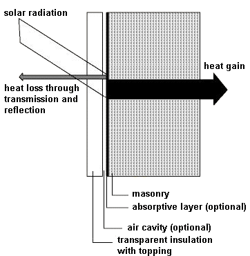 |
| Figure 3: Comparison of the energy pathways of opaque and transparent insulation. | |
Another type of thermal insulation is the green roof. The heat insulating properties of plants are based on various factors. The transmission losses are reduced by the enclosed air volume, acting as an insulation layer, and the emitted amount of long wave radiation is reduced by absorption and reflection at the plants leaves. A further function of the plant layer is the protection against wind. The thick layer of plants reduces air movement at the exterior surface of the structure and hence reduces the convective heat loss.
Green roofs are also suitable to reduce the summer overheating of the building.
The plant layer absorbs and reflects the short wave radiation from the sun.
The absorbed energy is then used through evaporative processes and photosynthesis
and adds therefore not to the heating of the building.
Implementation types
Basically there are three possibilities for the positioning of the insulation layer within a structural element. These are external, internal and core thermal insulation. The external one is the most favourable one. The whole building is enclosed within a gapless thermal skin. Thermal bridging and the under-cooling of the buildings structures are avoided. A special form of external insulation is the perimeter insulation which encloses all structural elements having soil contact. The perimeter insulation is positioned vertically at the basement walls and horizontally under the basements floor outside the buildings sealing layer. It has to meet structural stability criteria and long-term endurance to moisture exposition. An example for external insulation are the integrated insulation systems, which are also called a thermal skin. It consists of an insulation layer, a reinforced layer and a final coating. The reinforced layer and the final coating protect the insulation material against mechanical stress and effects of weather.
The core insulation is positioned in the cavity of a cavity wall. The cavity
is either completely or partially filled with the insulation material, leaving
space for an air gap, which can be used as an additional insulating layer or
to ventilate the cavity and hence quickens the drying of the insulation material.
The cavity insulation is used in renovations as well as in new buildings.
Internal insulation is preferred during renovations due to the fact that here
no problems are caused concerning the protection of historic buildings or other
civil rights. Disadvantages of this placement are, that the building construction
is under-cooled in winter and the hardly controllable difficulties related to
thermal bridges. Furthermore, the summer overheating problem is increased by
the reduction of the thermal capacity on the interior surfaces.
Material requirements
Insulation materials have to keep their shape, be durable and resistant against mould and parasites. The moisture balance of the construction has to be positive, i.e. the water accumulating inside the construction during the thawing period (winter) has to be removed to the exterior during the evaporating period (summer). The placement of a wind tight layer at the outer surface and an airtight on the inner surface prevent the insulation material form being perfused with humid and warm room air from the inside or cold ambient air from the outside. Depending on the field of use, the insulation material have to suffice the safety requirements for fire protection.
Sustainability and ecological evaluation
Insulation materials can be divided into organic and non-organic groups (mineral fibre, glass wool, perlites) according to their raw materials. Organic materials can be subdivided into natural (cork, cotton, wool) and synthetic (polyurethane rigid foam, polystyrene) materials.
From an ecological point of view it is possible to rate the insulation materials
according to the cumulative energy demand (CED) . Table 2 lists a selection
of common building materials and their CED`s.
|
||||||||||||||||||||||||
| Table 2: Cumulative energy demand and mass densities of common building materials [3,1]. |
Another possibility to ecologically rate the insulation materials is the material
intensity.
This rating includes the consumption of water, air and land during the manufacturing.
A further rating aspect is the health risk: Insulation materials should not
emit any unhealthy substances during their installation or later use.
Thermal bridges
Thermal bridges are regions of relatively high heat flow conductance in a building envelope caused by one of the following structural disturbances shown in figure 4 [4].
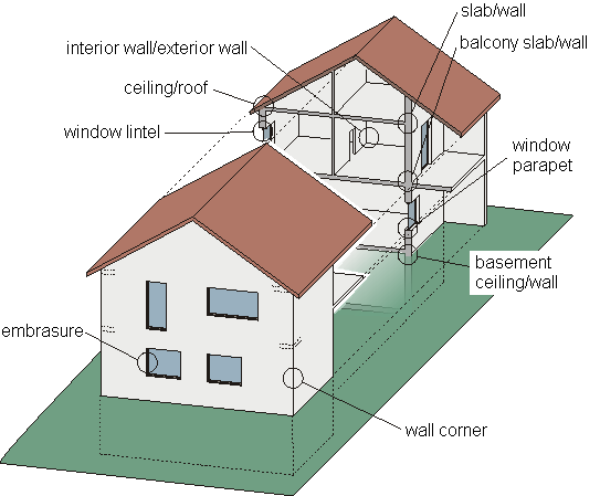 |
| Figure 4: Potential locations for thermal bridges if not carefully designed. |
Thermal bridges are categorised into four major groups:
Geometrical thermal bridges are created through an enlargement of the heat emitting or absorbing surface area. Examples are inner or outer corners (3-d thermal bridges) or room edges (2-d thermal bridges) of external partitions.
Thermal bridges related to material properties are located in areas where the thermal properties of one or several layers of a structural element are altered (e.g. concrete column in a brick wall, mounting equipment penetrating the element).
Thermal bridges related to mass flow are locations of material transport with energy transfer (air leakages, penetration of pipes through structural elements).
A further group is formed by special other thermal bridges. These aren't characterised by higher U-values than the surrounding structural elements, but by locally increased heat transmission caused by locally differing surface temperatures (radiator at an external wall).
Combinations of the above mentioned types are also possible.
Especially with well insulated buildings the avoidance of thermal bridges plays a major role, as the transmission losses through the thermal bridges can dominate the overall heat transmission losses. therefore avoiding unnecessary thermal bridges helps to save heating energy and hence to reduce the running costs and contributes to save the environment.
Another risk of thermal bridges are the low interior surfaces in winter caused
by the bad thermal insulation at these areas. Hereby the possibility of condensation
inside the structural element or at its inner surfaces increases. This can lead
to severe damages of the building and to the occurrence of mould.
These negative influences of the thermal bridges can be greatly reduced or even omitted by carefully planning the placement of the insulation layers.
Literature
[1] "Schutz vor Kälte und Hitze - Dämmstoffe im Vergleich", Broschüre der Energieagentur NRW, Wuppertal, Dezember 2001.
[2] RWE-Bauhandbuch, Ausgabe 12, Litdruck und Verlag GmbH, Oberhausen, 1998.
[3] Fachbereich für Ökologisch verträgliche Energiewirtschaft, Universität Essen, 2001
[4] "Stoffströme beim Modernisieren", Planungshilfe des Landesinstituts für Bauwesen NRW, Aachen, 2000.
[5] Hauser, G., Stiegel, H.: Wärmebrücken-Atlas für den Mauerwerksbau. Bauverlag GmbH, Wiesbaden und Berlin, 1993.